Hess-Lancaster Test


|
Hess-Lancaster Test |
|
The Hess-Lancaster test or Hess test is a test for binocular functions with separated images for both eyes. This clinical test is simulated by SEE++ with a "virtual patient" in order to enable comparison with real patient-measured data.
During the clinical Hess test the following steps are carried out:
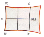
| 1. | The patient wears red-green-glasses with the red filter initially in front of the e.g. right eye (fixing eye). |
| 2. | The patient holds a green light pointer, the examiner holds a red light pointer. |
| 3. | The examiner projects a red light spot onto the so-called Hess screen and asks the patient to bring the green light spot (following eye) over the red light spot. Under normal conditions, both light spots overlay in all nine main gaze directions (see figure a). |
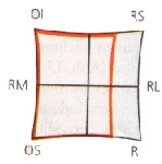
| 4. | Now the red filter is put in front of the other eye and the previous steps are repeated with the other eye, which is now the fixing eye. |
Possible Reactions of the Patient During the Hess Test
If the patient now fixates with the "normal" left eye, the fixation can be reached with "normal" innervation. However, if, for example, the right medial rectus muscle is paretic, then the patient's green light pointer will point at a spot that does not match with the correct direction (see figure c).
Another possible deviation occurs, if the patient for example has an abducens palsy on the right eye and is fixing with the same eye (red filter). Then the "normal" medial rectus muscle of the left eye receives an excessive innervation (Hering's law) and, as a consequence, the patient's green light pointer will point to a position on the screen, which lies far beyond the correct one (see figure b). After the test is finished, the relative positions are connected with straight lines.
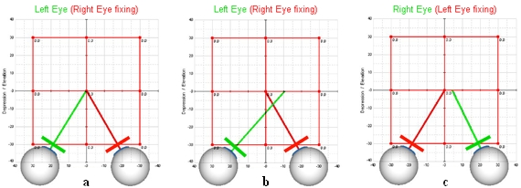
The results of the Hess test are normally two diagrams (left eye fixing and right eye fixing) with the corresponding gaze positions, which in turn show the deviation and the squint angle (see figure below).
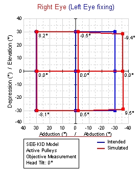
Example for a Left Eye Fixing During the Hess Test
In the Hess-diagram, the blue points represent those gaze positions which the patient should fixate (intended gaze positions) and the red points represent those gaze positions which the patient was able to reach with the following eye. The difference between the blue and the red points shows the respective deviation of the binocular coordination. At the same time, the torsion of the following eye is shown in textual form next to each red point (following gaze position). The following example gives an overview of the interpretation of Hess-diagrams for a medial rectus muscle paresis on the right eye:
|
|
||||||
|
|
|
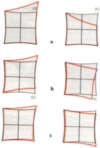
Changes in the Hess-diagrams are a prognostic help. For example, a paresis of the superior rectus muscle of the right eye will show a restriction of the affected muscle and a hyperfunction of the synergist (inferior oblique muscle of the left eye) (see figure a). As a result of this significant incomitant reaction shown in both diagrams, the diagnosis can be made directly out of the diagrams. But when the paretic muscle has recovered, both diagrams show approximately normal values again. If however the paresis persists, the shapes of both diagrams change and a secondary contracture of the ipsilateral antagonist (inferior rectus muscle of the right eye) develops, which can be seen as a hyperfunction in the diagram. |
This in turn can lead to a secondary (inhibition) palsy of the superior oblique muscle of the left eye, which becomes apparent as a reduced action in the diagram (see figure b) and which gives the false impression that the left superior oblique muscle is the real cause for the pathological situation. By-and-by the two diagrams get even more concomitant up to the point where it is impossible to determine which muscle was the primary paretic muscle (see figure c).
The SEE++ system does not provide a simulation of convalescence processes or healing progresses. Nevertheless, it offers the possibility to save the data of such processes, just as surgeries, in form of scenarios and makes it possible to reproduce such changes in the form of carefully chosen parameters in the force model.