Muscle Data


|
Muscle Data |
|
The muscle data dialog is one of the most central elements in the SEE++ system. It can be used to adjust the force model to pathological conditions regarding to single eye muscles. All data contained in this dialog changes the force development of all or some particular muscles. Therefore, muscle paresis, hyperfunctions and fibrosis can be simulated.
The muscle data exists for each eye simulated by SEE++ (left eye, right eye and reference eye). In this explanation the left eye is used exemplary again.
You can access this dialog via the main menu under "Data->Left Eye->Muscles" or via the Treeview under "Medical Data->Left Eye->Muscle Data". The dialog consists of various "tab sheets", whereas each tab sheet represents one of the six eye muscles. Additionally, the tab sheet "General" summarizes the settings that are applied on the whole model. Simply choose your desired tab sheet by clicking on the corresponding heading with the left mouse button. Another possibility to directly access the tab sheet of a muscle is to perform a short double-click with the left mouse button on an insertion point in the 3D-view.
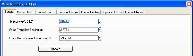
By default this dialog is displayed with the active tab sheet "General". It can be used to change the three general parameters of the force model. Confirm your changes by hitting the "OK" button or discard them by clicking on "Cancel". The button "Update" allows an immediate update of all changes without the need to close the dialog. That means that SEE++ instantly performs the calculation of the Hess-Lancaster-Test with the changed values. This option is useful if, additionally to the general settings, changes to muscle-specific parameters will be made before closing the dialog.
If you now choose one of the tab sheets, you will recognize that the different sheets are (nearly) identical for all muscles:
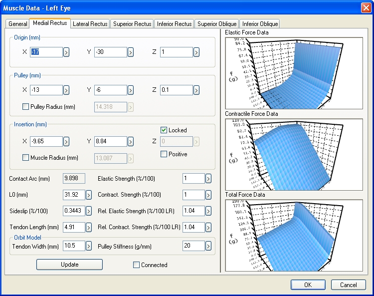
First of all this dialog provides the possibility to manually change some geometric properties (origin, pulley and insertion) of a muscle. All coordinates have to be specified according to the chosen eye in the defined head fixed coordinate system. These parameters cause a change of the muscle path and therefore influence the simulation result. All values are defined in primary position. That means that even when the 3D-view displays another eye position, the geometric values of the muscle dialogs always refer to the primary position. If you want to know the geometric values of a certain gaze direction, you can use the Stateviewer to get that information.
The visualization of the three muscle curves on the right hand side of the dialog is based on the 3D-view. Each diagram is an independent view and can be arbitrarily rotated, scaled, printed and saved as an image. The checkbox "Connected" is used to equate the view of the single curves among each other. That means that if you change the view of one 3D-curve with your mouse and the "Connected" checkbox is checked, all other curves follow automatically.
The "Update" button allows an immediate update of all changes without the need to close the dialog with "OK" in the same manner as already described for the "General" tab sheet. SEE++ immediately starts with the recalculation of the simulation results in the background after clicking on "Update".
The following possibilities exist to modify the visualization of the 3D-muscle-curves:
While navigating with the mouse, first always click into the muscle curve with one mouse button, keep the button pressed and then move the mouse while still pressing the mouse button. Simply release the mouse button to stop.
Mouse Button/Button |
Action |
Left mouse button |
Rotate the whole muscle curve (camera rotation) with the help of a "virtual hemisphere". Within this sphere the rotation is done around the x- and z-axes and outside around the y-axis. |
Rotate the mouse wheel or
|
Zoom in or zoom out the whole view (zoom function). |
Click the mouse wheel or middle mouse button |
Reset the 3D-view to the initial position (camera reset). |
|
Reset the view of all three 3D-muscle-curves to the initial position (camera reset). |
Right mouse button |
Open the menu for the display options. |
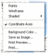
In a 3D-curve the menu for the display options is opened by clicking the right mouse button.
|
The curve view can be displayed in three different ways: •Points - the muscle curve is displayed as points •Wireframe - displays a wireframe model of the curve •Shaded - choose between a stripes or quadrangle view
|
The option "Coordinate Axes" shows or hides the whole diagram marking. The function "Background Color..." allows to change the background color of the diagram.
If you choose "Save as Image...", the dialog to save an image is displayed. The functions "Print..." and "Print Preview..." open the appropriate Windows® default dialogs.
Change the Pulley Position
Basically, the pulley of a muscle can be moved arbitrarily in the 3D space. This task is hard to achieve manually. Therefore, the checkbox "Pulley Radius" allows you to enlarge or decrease the distance to the rotation center of the globe (coordinate system zero point). If you click on the checkbox with the left mouse button so that it is ticked and adapt the pulley radius, the coordinates of the pulley in x-, y- and z-direction are automatically calculated via the distance formula of the vector to the zero point of the coordinate system.
Change the Insertion
The insertion point of a muscle usually is directly coupled to the globe. Therefore, a "free" positioning in the 3D space is hard to estimate. The checkbox "Locked" allows to automatically define the z-coordinate via insertion into the spherical equation of the globe, so that only the x- and y-coordinate are arbitrary. Choosing the x- and y-coordinates in an adequate way still permits two possibilities to position the insertion point on the globe (front or back hemisphere). This is achieved by ticking off the checkbox "Positive". If the checkbox "Positive" is ticked, the z-coordinate of the calculated insertion point is used, that points along the positive z-axis direction of the used coordinate system.
Another possibility to define an insertion point of a muscle is to use the checkbox "Muscle Rad.". The same principle such as the one used by the determination of the pulley position via the "Pulley Radius" is applied here. The insertion point is displaced according to the "Muscle Radius" along the vector pointing to the origin of the used coordinate system.
|
The geometric abstraction of the globe is reduced to a sphere. However, a real globe is unlikely to be based on a perfect sphere. Therefore, it is possible, that in the 3D-view some muscles do not directly touch the globe in the area of the insertion. Since the insertion points used in SEE++ were measured as complete 3D points and were defined according to an ellipsoid shaped globe, a separate "virtual" globe radius is assigned to each muscle. |
Change the Muscle-Specific Parameters
The muscle-specific parameters form the core of the configurable muscle model. The specific force data (contractile, elastic and total force) can be directly influenced here. The value "Contact Arc" is not changeable and therefore forms an exception. This value displays the contact arc of a muscle in primary position, resulting of the geometrical properties as a spherical distance between the insertion point and the point of tangency. The values have to be adopted according to the explanations denoted in the chapter describing the "force model".
 + left mouse button